Categories
Series 55 Training
 AVK SUPPORT
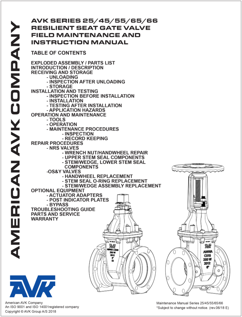
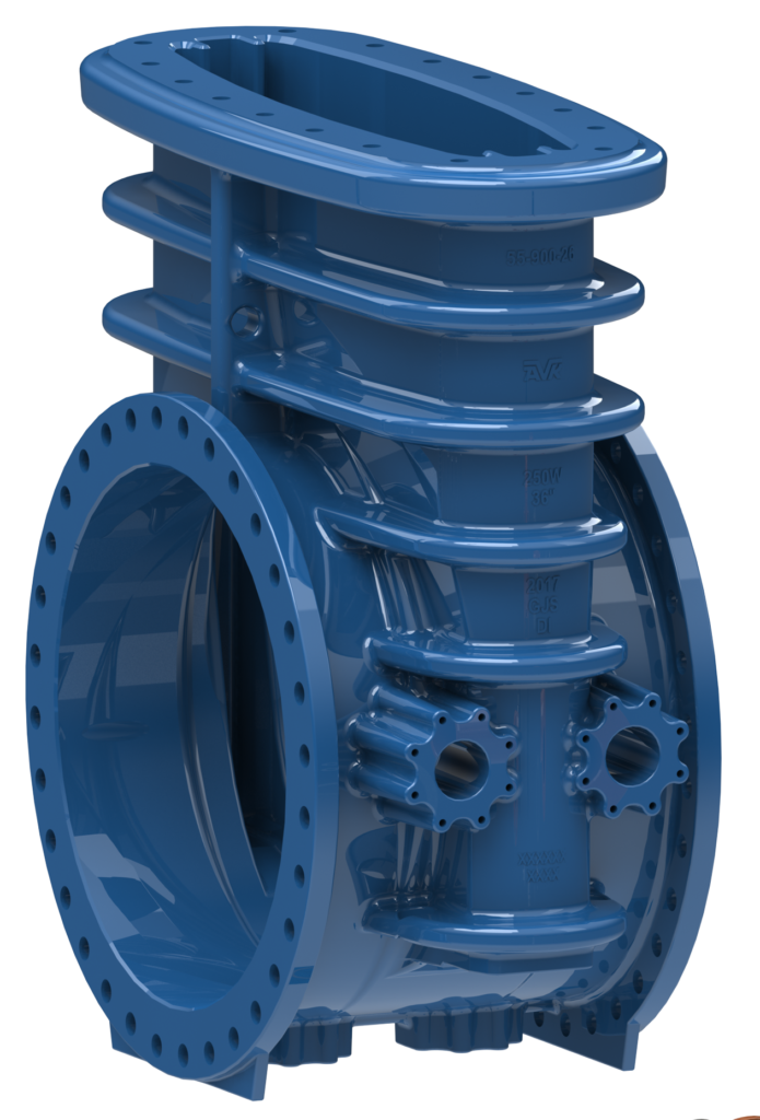
MJ x MJ gate valve to AWWA C515 for water and other neutral liquids to 160°F
AVK gate valves are designed with built-in safety in every detail. The wedge is fully vulcanized with AVK’s own EPDM rubber compound with NSF drinking water approval. It features an outstanding durability due to the ability of the rubber to regain its original shape, the double bonding vulcanization process and the sturdy wedge design. The triple stem seal system, the high strength stem and the thorough corrosion protection safeguard the unmatched reliability.
Leakage between valve and actuator: Replace O-rings
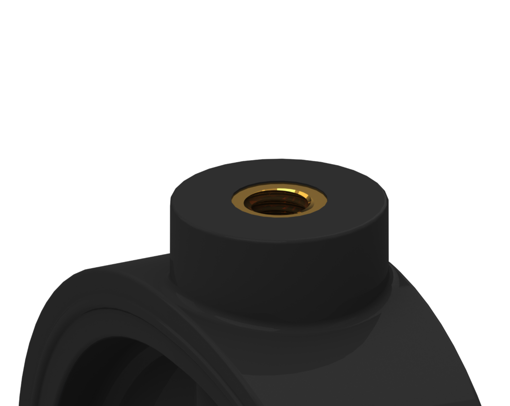
Bottom Trunnion is Leaking: Remove plug and replace O-ring
Leakage at flanges: Tighten Flange Bolts
Valve leaks when closed:
Verify the valve is within its pressure range.
Open and close the valve a few times to flush away any debris that may be in the seating area.
Check that the actuator bolts are tight and the actuator is not rotating back and forth when the valve is operated.
Check that the disc is centered in the valve body. Adjust actuator if necessary. See Stop Nut Adjustment below.
Check that the metal disc edge is free of scale and scratches. If damaged the valve must be returned for repair
Check that the rubber seat is not damaged. The rubber seat is bonded to the valve body and cannot be replaced.
If a new rubber seat is required contact Customer Service for authorization and instructions.
REPAIR PROCEDURES
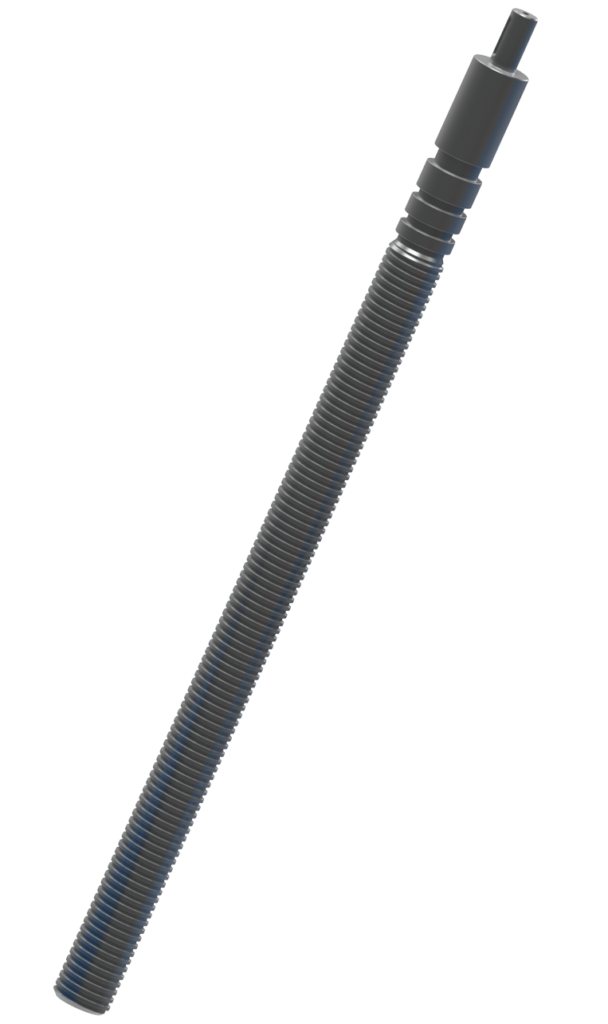
Stem Seal Replacement.
WARNING: Depressurize the line before performing this operation.
1. Remove the actuator
a. Open the valve halfway
b. Remove the actuator mounting bolts
c. Carefully slide the actuator from the valve stem. Do not lose the actuator plate pins or stem keys.
2. Remove the stem cover plate.
3. Using a small tool pull the upper o-ring packing ring off the valve stem
L4. Using the same tool remove the o-ring
5. Insert a new o-ring
6. Replace the packing ring
7. Replace the stem cover plate
8. Reinstall the actuator
a. Place the actuator on the stem. Use the keys for round stems
b. Reinstall the actuator mounting bolts and tighten loosely.
c. Reinsert the plate pins.
d. Tighten the actuator bolts to 90 ft-lbs
Leakage, broken parts, hard operation, and other defects should be corrected by a repair crew as soon as possible
after the defect has been reported. If repairs are to be performed in the field, the repair crews should take a full complement of spare parts to the jobsite. Provisions should be made to isolate the defective valve from water pressure and relieve internal trapped pressure prior to performing any corrective maintenance. Disassembly of the valve should be accomplished in accordance with the procedure supplied in the following sections. After repairing the valve, the operating mechanism should be cycled through one complete operating cycle. With full line pressure applied to the valve in the open position, an inspection should be made to detect leakage in the areas around the seal plate, bonnet, packing gland, and body-end connections. A record should be made to indicate that the valve has been repaired and is in working

Lcondition. Any marking that the valve is inoperable should be removed. In addition, fire department and other appropriate municipal departments should be informed
of satisfactory repair of the valve.
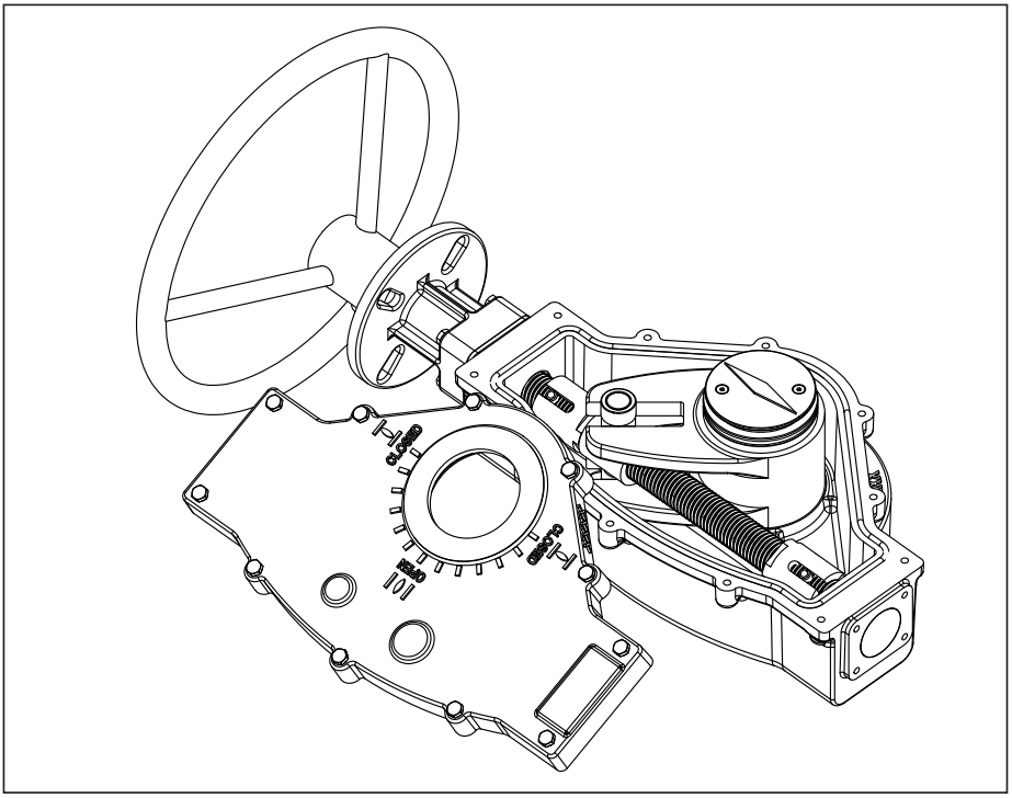
UPPER O-RING RETAINER,
O-RING REPLACEMENT
Note: Shut off the pressurized pipeline and depressurize it.
1. Turn the Disc Assembly (F807) to the closed position.
2. Support the Gearbox (F811) safely.
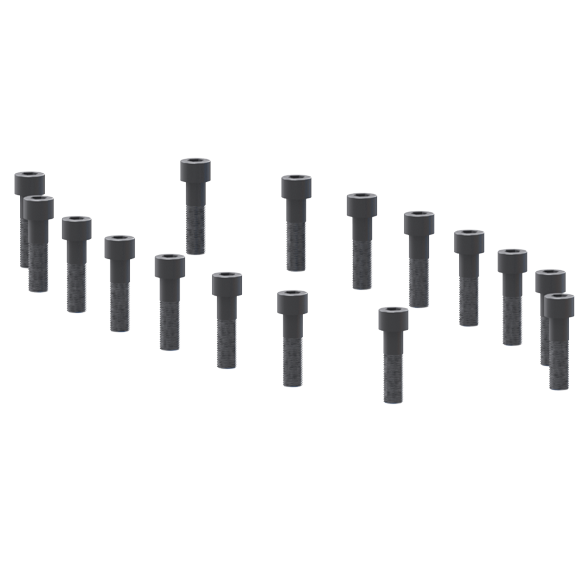
3. Remove the Gearbox Bolts (F814) using an open end wrench.
Set the Gearbox Bolts (F814), and Gearbox Washers (F815)
aside for use during re-assembly. (See Fig. 2A)
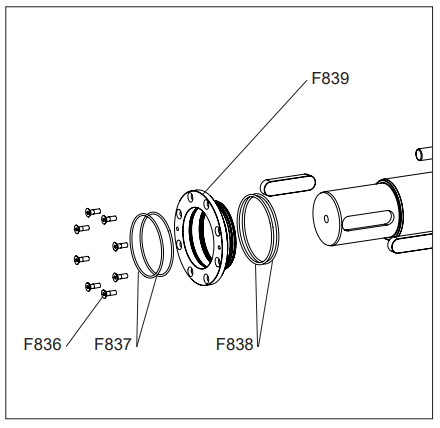
4. Remove the eight, Upper O-ring Retainer Screws (F836)
from the Upper O-ring Retainer (F839) using an allen wrench.
(See Fig. 2B)
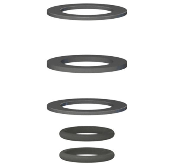
5. Remove old, Upper O-ring Retainer Inner O-rings (F837) and
Upper O-ring Retainer Outer Orings. (F838)
6. Clean Seal House. (F839)
7. Grease and install new o-rings.
8. Re-install in reverse order and tighten screws.
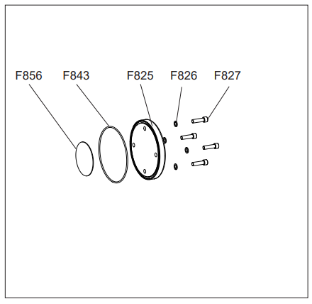
END PLATE O-RING REPLACEMENT
Note: Shut off the pressurized pipeline and depressurize it.
1. Turn the Disc Assembly (F807) to the closed position.
2. Remove the four End Plate Bolts (F827), End Plate Washers
(F826), and End Plate (F825) using an allen wrench.
(See Fig. 2C)
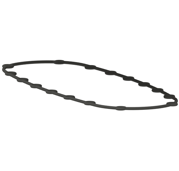
3. Remove old End Plate Dust O-ring (F843) and Axial Thrust
Bearing Gasket (F856).
4. Clean End Plate. (F825)
5. Grease and install new o-ring. Replace Axial Thrust
Bearing Gasket (F856).
6. Re-install in reverse order and tighten screws
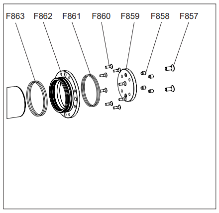
LOWER O-RING RETAINER,
O-RING REPLACEMENT
Note: Shut off the pressurized pipeline and depressurize it.
1. Follow intructions to remove End Plate.
2. Remove the four End Plate Bolts (F827), End Plate Washers
(F826), and End Plate (F825) using an allen wrench.
(See Fig. 2C)
3. Remove old End Plate Dust O-ring (F843) and Axial Thrust
Bearing Gasket (F856).
4. Clean End Plate. (F825)
5. Grease and install new o-ring. Replace Axial Thrust
Bearing Gasket (F856).
6. Remove the eight Lower O-ring Retainer Mounting Screws
(F860) (See Fig. 2D)
7. Remove the Lower O-ring Retainer (F862), along with the
Lower O-ring Retainer Inner O-rings (F861), and Lower O-ring
Retainer Outer O-rings (F863).
8. Remove the old o-rings from the Lower O-ring Retainer
(F862).
9. Clean the Lower O-ring Retainer (F862) and install new orings
(F861) and (F863).
10. Re-install in reverse order and tighten screws.
| Cookie | Duration | Description |
|---|---|---|
| cookielawinfo-checkbox-analytics | 11 months | This cookie is set by GDPR Cookie Consent plugin. The cookie is used to store the user consent for the cookies in the category "Analytics". |
| cookielawinfo-checkbox-functional | 11 months | The cookie is set by GDPR cookie consent to record the user consent for the cookies in the category "Functional". |
| cookielawinfo-checkbox-necessary | 11 months | This cookie is set by GDPR Cookie Consent plugin. The cookies is used to store the user consent for the cookies in the category "Necessary". |
| cookielawinfo-checkbox-others | 11 months | This cookie is set by GDPR Cookie Consent plugin. The cookie is used to store the user consent for the cookies in the category "Other. |
| cookielawinfo-checkbox-performance | 11 months | This cookie is set by GDPR Cookie Consent plugin. The cookie is used to store the user consent for the cookies in the category "Performance". |
| viewed_cookie_policy | 11 months | The cookie is set by the GDPR Cookie Consent plugin and is used to store whether or not user has consented to the use of cookies. It does not store any personal data. |