Categories
Uncategorized

Series 766 In-Depth

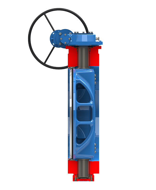
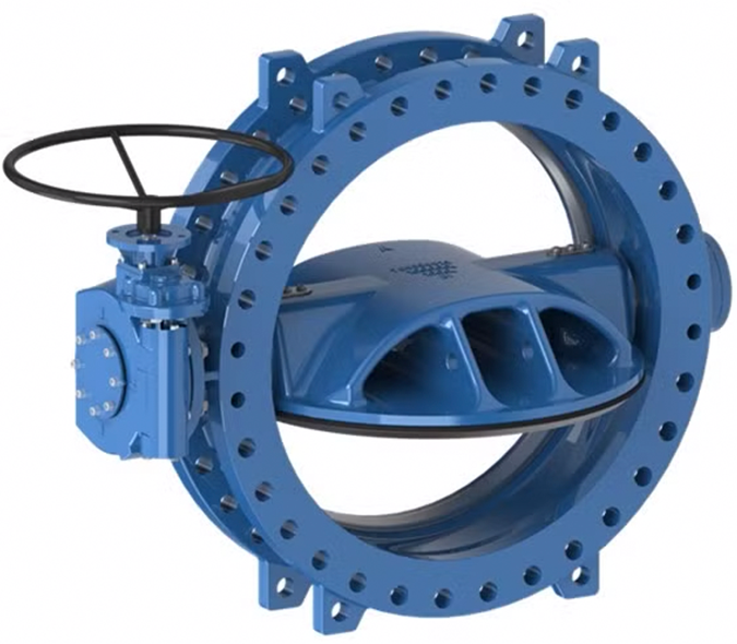
Double eccentric Butterfly Valve with rubber seal around the disc, AWWA 504, NSF61 certified, for drinking water and neutral liquids to max 160°F.

Available in Flanged, Wafer, Mechanical Joint, and Mechanical Joint by Flanged end configuration

Features

  • Double eccentric design causes the seal compression to release after just a few degrees of opening reducing operating torque
  • Flow-through disc with a stiff, light weight box-design for high flow velocity applications; low sensitivity to cavitation prevents turbulent flow
  • Rubber seal around the disc circumference held in place by an SS316 disk ring
  • Drinking water approval for all rubber parts in contact with the water
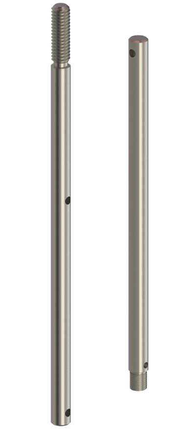
  • Shaft in stainless steel
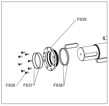
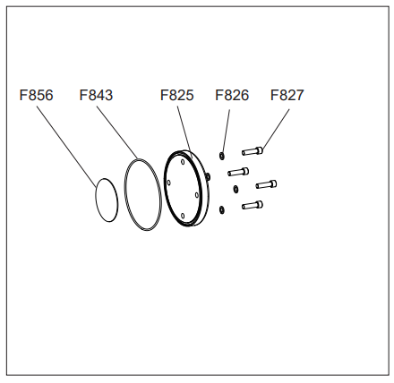
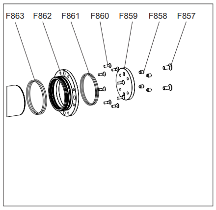
  • Anti blow-out shaft design with replaceable O-ring shaft seal and self lubricating bronze/PTFE radial bearings. A replaceable POM disc at the end of the stub shaft serves as thrust bearing
  • Shaft ends fully encapsulated in disc and fixed with dowels corrosion protected with O-rings and a stainless steel security plate; a safety key backs up the dowel connection
  • Gearbox in IP68 with handwheel and position indicator
  • Fasteners in stainless steel A4
  • Body and disc of ductile iron coated with blue RAL 5017 fusion bonded epoxy to AWWA C550, GSK, and approved by WRAS-DVGW/W270/UBA
Categories
Uncategorized

Series 766 Training

Series 766 - O-Ring Replacement

Leakage, broken parts, hard operation, and other defects should be corrected by a repair crew as soon as possible
after the defect has been reported. If repairs are to be performed in the field, the repair crews should take a full complement of spare parts to the jobsite. Provisions should be made to isolate the defective valve from water pressure and relieve internal trapped pressure prior to performing any corrective maintenance. Disassembly of the valve should be accomplished in accordance with the procedure supplied in the following sections. After repairing the valve, the operating mechanism should be cycled through one complete operating cycle. With full line pressure applied to the valve in the open position, an inspection should be made to detect leakage in the areas around the seal plate, bonnet, packing gland, and body-end connections. A record should be made to indicate that the valve has been repaired and is in working 

Lcondition. Any marking that the valve is inoperable should be removed. In addition, fire department and other appropriate municipal departments should be informed
of satisfactory repair of the valve.
UPPER O-RING RETAINER,
O-RING REPLACEMENT
Note: Shut off the pressurized pipeline and depressurize it.
1. Turn the Disc Assembly (F807) to the closed position.
2. Support the Gearbox (F811) safely.
3. Remove the Gearbox Bolts (F814) using an open end wrench.
Set the Gearbox Bolts (F814), and Gearbox Washers (F815)
aside for use during re-assembly. (See Fig. 2A)
4. Remove the eight, Upper O-ring Retainer Screws (F836)
from the Upper O-ring Retainer (F839) using an allen wrench.
(See Fig. 2B)
5. Remove old, Upper O-ring Retainer Inner O-rings (F837) and
Upper O-ring Retainer Outer Orings. (F838)
6. Clean Seal House. (F839)
7. Grease and install new o-rings.
8. Re-install in reverse order and tighten screws.

END PLATE O-RING REPLACEMENT
Note: Shut off the pressurized pipeline and depressurize it.
1. Turn the Disc Assembly (F807) to the closed position.
2. Remove the four End Plate Bolts (F827), End Plate Washers
(F826), and End Plate (F825) using an allen wrench.
(See Fig. 2C)
3. Remove old End Plate Dust O-ring (F843) and Axial Thrust
Bearing Gasket (F856).
4. Clean End Plate. (F825)
5. Grease and install new o-ring. Replace Axial Thrust
Bearing Gasket (F856).
6. Re-install in reverse order and tighten screws

LOWER O-RING RETAINER,
O-RING REPLACEMENT
Note: Shut off the pressurized pipeline and depressurize it.
1. Follow intructions to remove End Plate.
2. Remove the four End Plate Bolts (F827), End Plate Washers
(F826), and End Plate (F825) using an allen wrench.
(See Fig. 2C)


3. Remove old End Plate Dust O-ring (F843) and Axial Thrust
Bearing Gasket (F856).
4. Clean End Plate. (F825)
5. Grease and install new o-ring. Replace Axial Thrust
Bearing Gasket (F856).
6. Remove the eight Lower O-ring Retainer Mounting Screws
(F860) (See Fig. 2D)
7. Remove the Lower O-ring Retainer (F862), along with the
Lower O-ring Retainer Inner O-rings (F861), and Lower O-ring
Retainer Outer O-rings (F863).
8. Remove the old o-rings from the Lower O-ring Retainer
(F862).
9. Clean the Lower O-ring Retainer (F862) and install new orings
(F861) and (F863).
10. Re-install in reverse order and tighten screws.

Categories
Uncategorized

Series 67 In Depth

AVK Series 67 Post Flushing Hydrant

AVK POST/FLUSHING HYDRANT, 1 HOSE NOZZLE

Options Shown: 1×2.5″ NST hose, 304 bolting , 304 upper stem, 1.5″ pent. op.nut, Chain, Red

Post/Flushing Style Monitor for use in Water Distribution Systems

The American AVK Series 2700 Modern Hydrant is designed to be a trouble free, easy to maintain hydrant.

 
Variant 67/00-001
Material:Ductile Iron
PN:250 psi
Closing direction:Open Left

Features

  • Stainless steel upper stem – standard


  • Breakable flange and stem coupling – standard


  • EPDM encapsulated one-piece main valve – standard


  • Fusion Bonded Epoxy Coated Shoe with integral foot for easy installation – standard


  • Rated to 250 psi working pressure – standard


  • All ductile-iron construction


  • All internal working parts are removable from the top for easy maintenance


  • Any bury depth available


  • Self draining to prevent freezing


  • Bronze drain ring and main valve seat


  • Optional stainless steel lower stem


  • Open left or open right