AVK Series 66 HDPE Gate Valves
Operation and Maintenance
Series 66 HDPE Gate Valve Repair
STEM/WEDGE, LOWER STEM SEAL COMPONENT REPAIR:
WARNING: To perform the following steps, be sure the Water Main Supply Line has been shut off, and that the pressure has been bled off! Also provide sufficient clearing around the valve so that no soil or debris may fall into it.
1. Complete steps 1 through 4 in the UPPER STEM SEAL COMPONENT REPAIR section.
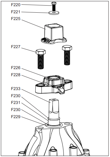
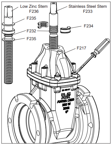
2. Turn the Stem (F333), in a closing direction until it disengages from the Wedge (F237), and remove from valve.
3. If applicable, for Low Zinc Stems, remove the Lower Anti Friction Washer (F235) from the recess in the bonnet (F217). For Stainless Steel Stems, the Stem Collar and Anti-Friction Washers are replaced by a two-piece Thrust Collar (F234). No Anti- Friction are necessary or present. The Lower Stem Seal O-ring (F232) should be present on the stem and in it’s own groove, located directly above the threads.
NOTE: On Stainless Steel Stems, the upper three grooves are for locating the Thrust Collar.


4. Inspect and replace any damaged parts.
NOTE: Use a food grade grease that contains no acetate or silicone on the new o-rings.
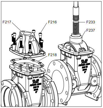
5. Using a small, flat bladed screwdriver, remove the hot melt glue that covers the Bonnet Bolts (F216).
6. Once the hot melt glue has been removed, use a 3/8”, or 10mm Allen wrench to remove the Bonnet Bolts (F216). Remove the Bonnet (F217) and Bonnet Gasket (F218) and set aside.
7. To remove the Wedge (F237) it is sometimes helpful to thread the Stem (F233) back into the wedge and use the stem as a handle or lever to extract the wedge. This is helpful with the larger sizes, (10” and 12”) valves.
8. Carefully inspect the interior of the valve body and remove any debris.
9. Inspect and replace any damaged parts and re-assemble in reverse order, torquing the Bonnet Bolts to 40 ft. lbs., in a diametrically opposed (180 degrees apart) pattern. 9. To replace the protective hot melt glue over the Bonnet Bolts, use any EPA approved caulk, or hot melt glue.