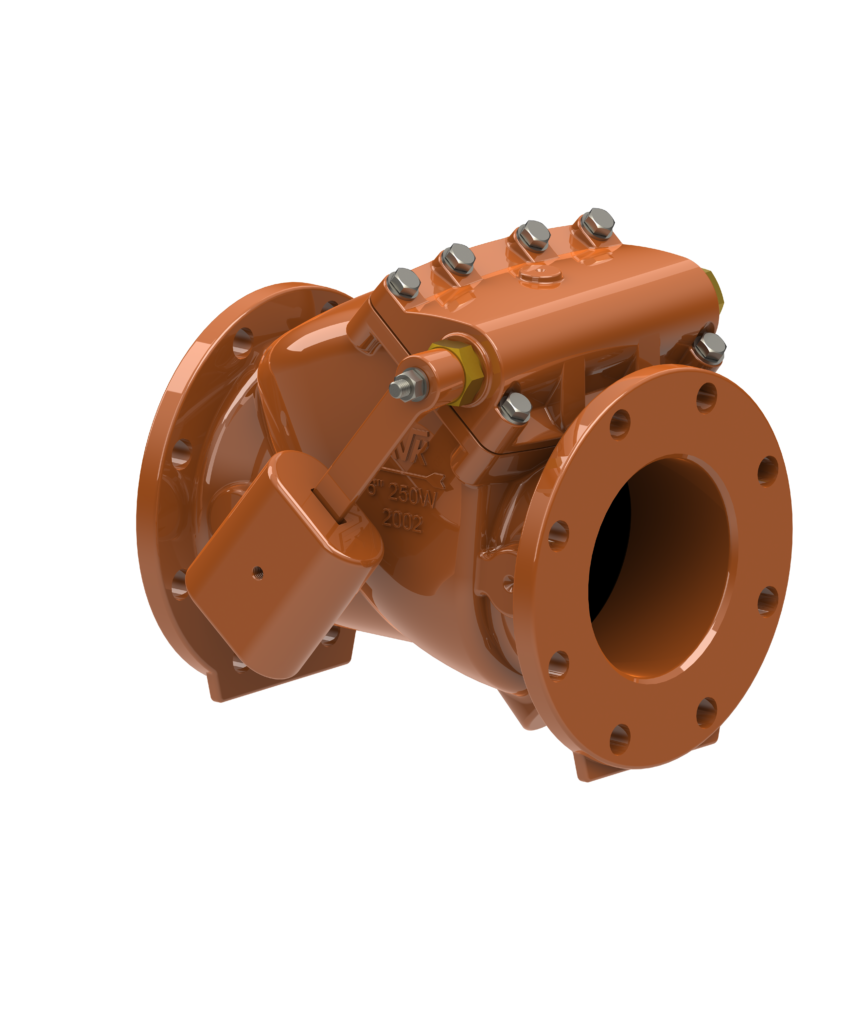
AVK Series 41 Swing Check Valve Lever and Weight and Spring and Weight Installation
LEVER AND WEIGHT
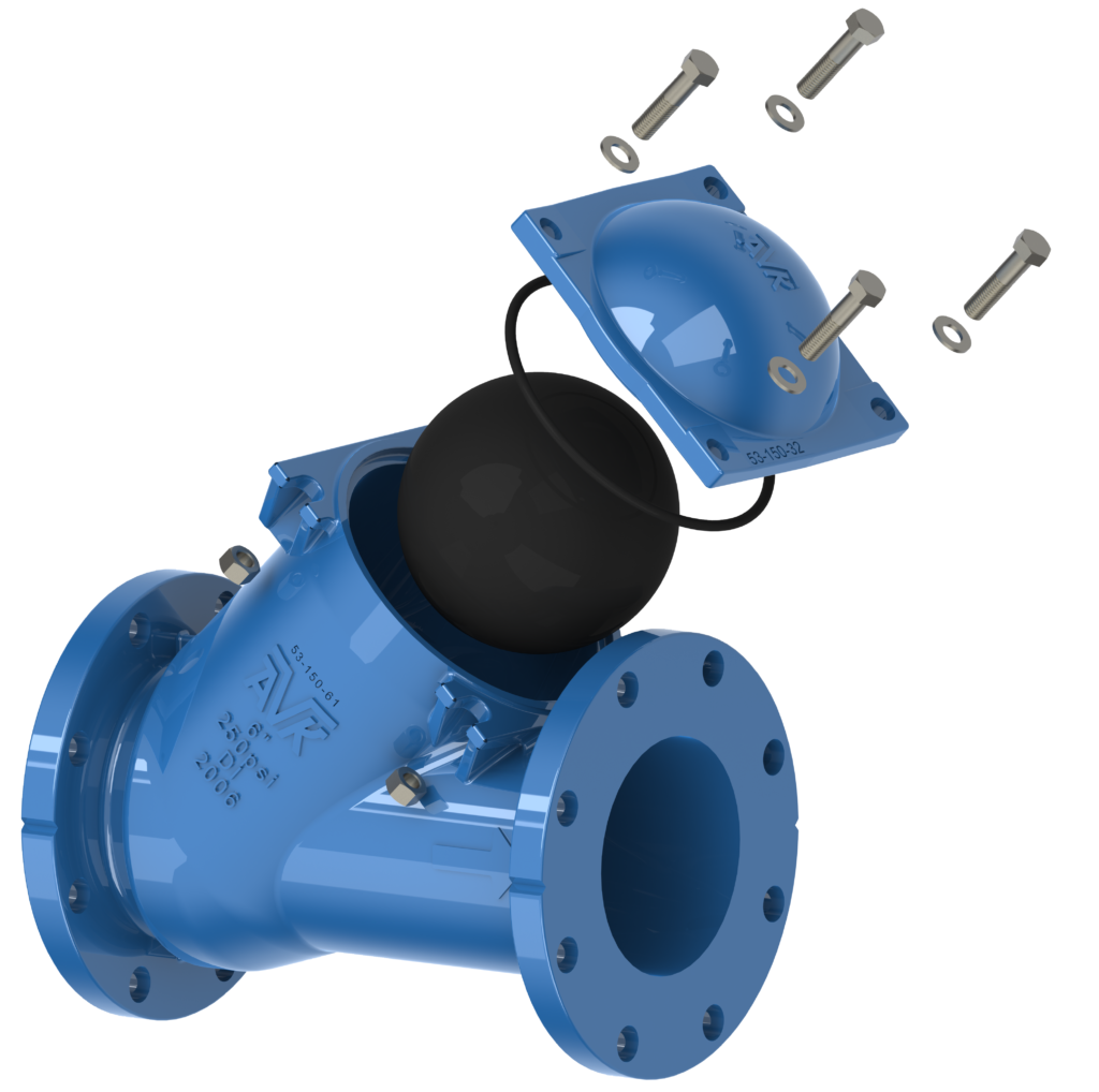
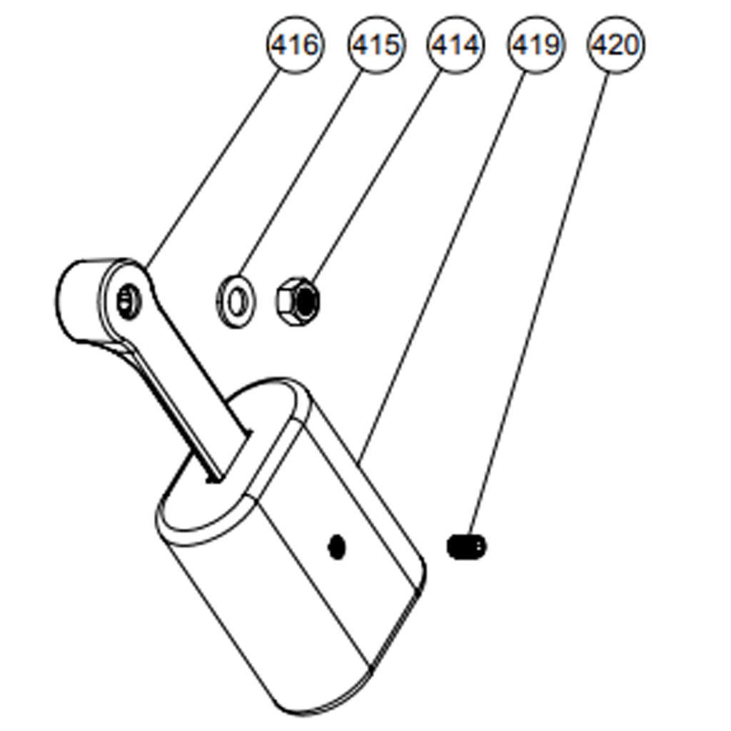
Once the valve is properly installed, the lever and weight assembly needs to be attached to the Shaft (408) passing
through the Open Bushing (417) in the Bonnet (407). Slide the Lever (416) onto the Shaft (408) and position as shown in
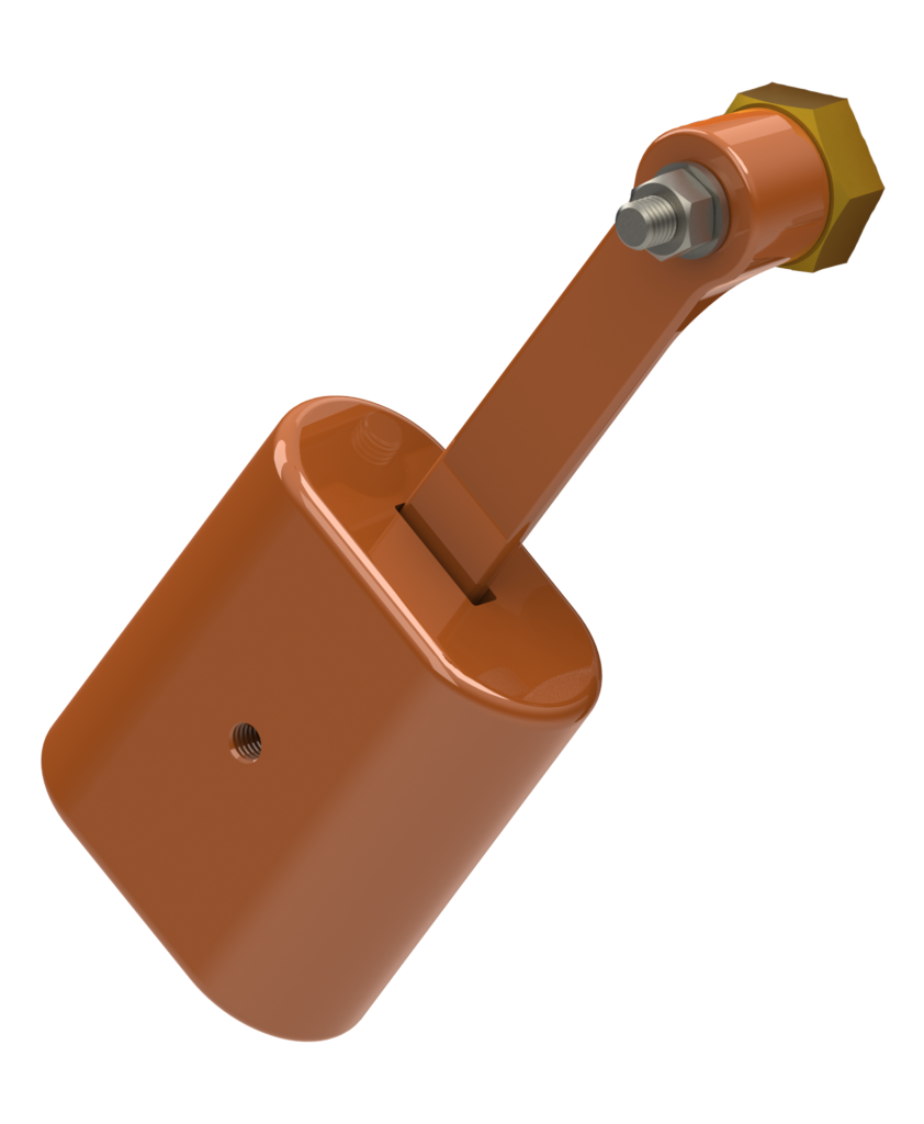
figure 4. Secure the Lever with the Shaft Washer (415) and Shaft Nut (414) and tighten to 30 ft-lbs. Attach the Weight (419)
and tighten the Set Screw (420) to hold the weight in place. A medium strength thread locking compound such as Locktite 242
should be used to attach the Lever and Weight.
WARNING: The weight can be moved on the lever to adjust closing speeds for optimum performance. DO not adjust
the weight while the system is operation. Serious injury can occur.
LEVER AND SPRING 3″- 8″
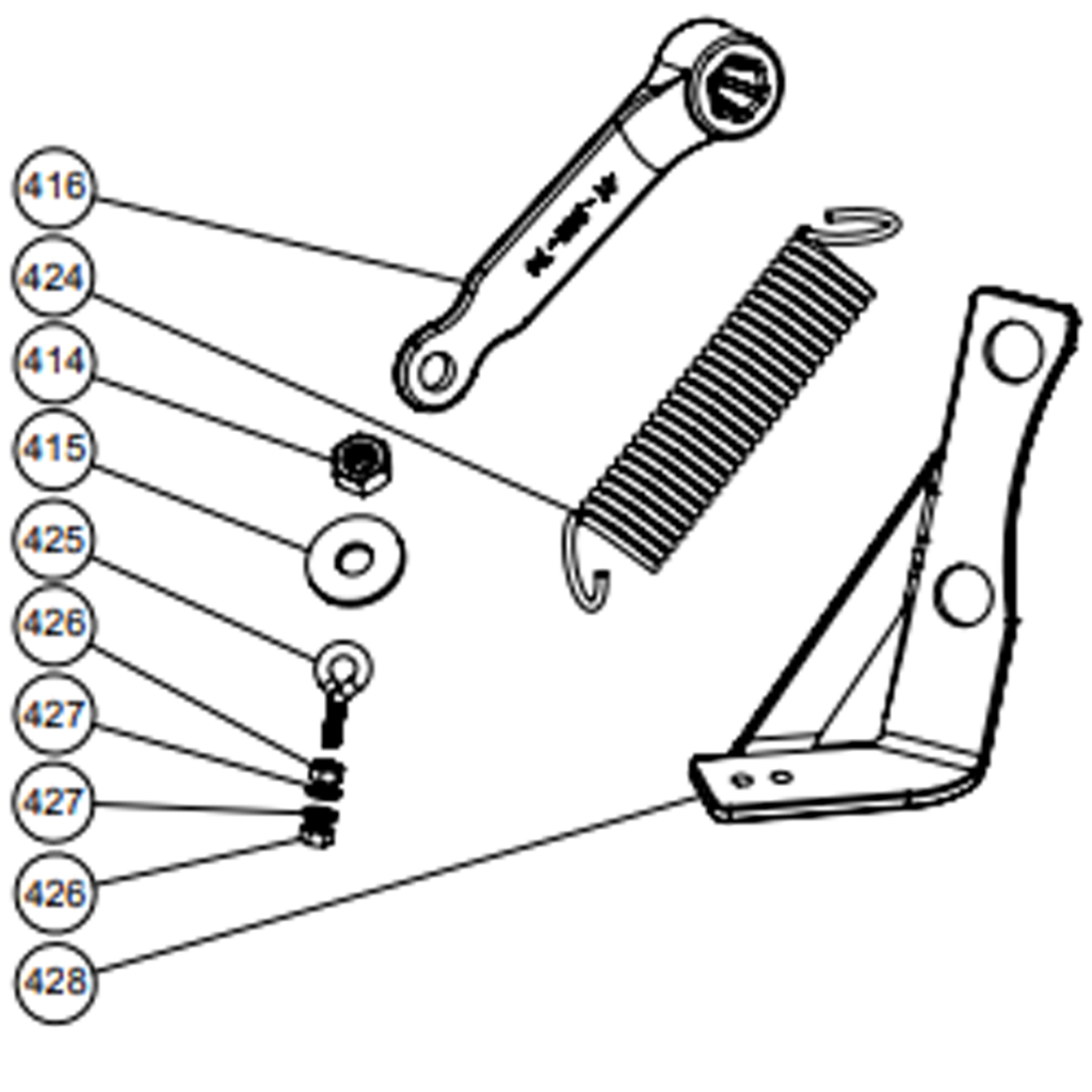
For sizes 3-inch through 8-inch, the Spring Bracket (428) must be installed using the flange mounting hardware
(figure 6). Install the Spring Eyebolt (425) on the Spring Bracket, securing it with the Spring Eyebolt Nuts (426), and Spring
Eyebolt Washers (427), one washer and nut on each side of the Spring Bracket (428). Slide the Lever (416) onto the Shaft
(408) and position as shown in figure 4. Secure the Lever with the Shaft Washer (415) and Shaft Nut (414) and tighten to 30
ft-lbs. Attach Spring (424) in it’s relaxed position as shown in figure (6).A medium strength thread locking compound such as
Locktite 242 should be used to attach the Lever.
LEVER AND SPRING 10″-12″
For Lever and Spring equipped 10-inch and 12-inch swing check valves, the Lever and Spring Assembly is installed
at the factory.