
Mysterious Origins
Do you know who invented the fire hydrant? Neither do we. In fact, no one truly knows who invented the first fire hydrant system. However, we do know that it was invented in Philadelphia, Pennsylvania in the early 1800s.
The patent with the name of the true inventor was destroyed, and nobody is exactly sure how. There are stories of fire, floods, and even an argument that caused the destruction of them. On the other hand, we don’t know for sure who was the first to invent them. However, credit for inventing the first fire hydrant system is often given to Frederick Graff, Sr. We do know for a fact that he created the first pillar fire hydrant in 1801. Subsequently, that is the reason why he receives credit for it today.
Frederick Graff was the chief engineer of the Philadelphia Water Works company. If you can believe it, he was still in his twenties when he invented the pillar hydrant system. However, there is no other evidence that he was truly the person who invented the first hydrant system. Unfortunately, the answer to that mystery has been lost to time.

Before The Fire Hydrant
We’ve come a long way in fire safety since the invent of the hydrant system. Prior to hydrants being available, firefighters used buckets of water to extinguish fires. While this might sound laughable now, these bucket brigades were the best system we had. Firefighters stood in a line between the fire and the source of water and passed buckets along, one by one until the fire was extinguished.
As you can imagine, this process was extremely slow, took a lot of manpower, and wasn’t particularly effective. This system is a major reason why fires used to destroy so much more property before the hydrant system was invented.
What Types of Fire Hydrant Systems Are There?
We’ve already discussed that Graff invented the first pillar system, but what exactly does that mean? Well, you might see different types of hydrants all around the world. But there are two basic fire hydrant systems: wet barrel systems and dry barrel systems.
Wet Barrel Systems
“Wet Barrel” fire hydrants have a multitude of advantages. And that is why they are extremely popular where freezing is not an issue. We call it a “wet” barrel system because there is always water flowing and supplied inside of it. So, when a firefighter attaches their fire hose to the valve, they are immediately supplying water to where they need it.
It is also not possible for people to open the valves to cool themselves off on hot summer days. This might seem like an innocent way to have fun. But it can have very troublesome effects when there is an emergency.
Wet barrel hydrants that are constructed well have a life expectancy of over 100 years, which isn’t a phrase you can say about most things. Unfortunately, the earliest hydrants from the 1800s can’t be restored to service because of their lead valves, which can be a health safety hazard.
Dry Barrel System
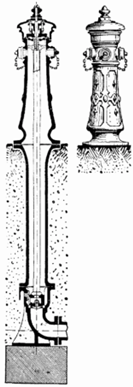
It’s common knowledge that water expands when it freezes. It’s why our pipes can burst in our homes during the winter. So, have you ever wondered why fire hydrants on the street don’t freeze and burst? There’s water in there, right? Well, not always.
In a dry barrel system, the water stays out of the part of the hydrant we see. It is stored below ground, where the Earth’s temperature is a steady 50 degrees Fahrenheit. If you know anyone who uses geothermal heating in the winter for their home, it is the same concept. While the temperature above ground can fluctuate drastically, the temperature below the Earth’s surface is constant, and freezing is not an issue.
When it is needed for use, firefighters open a valve on top to put their hose in. This opens the drain valve inside of the hydrant and allows water to come through. If the valve on the surface is closed, the drain valve will open and allow water to drain from the barrel, and it closes when all the water has escaped.