 AVK SUPPORT
Expect... AVK
AVK SUPPORTADJUSTING THE TARGET (FOR SERIES 3400
TYPE INDICATORS):(For assemblies made after 8/12)
NOTE:
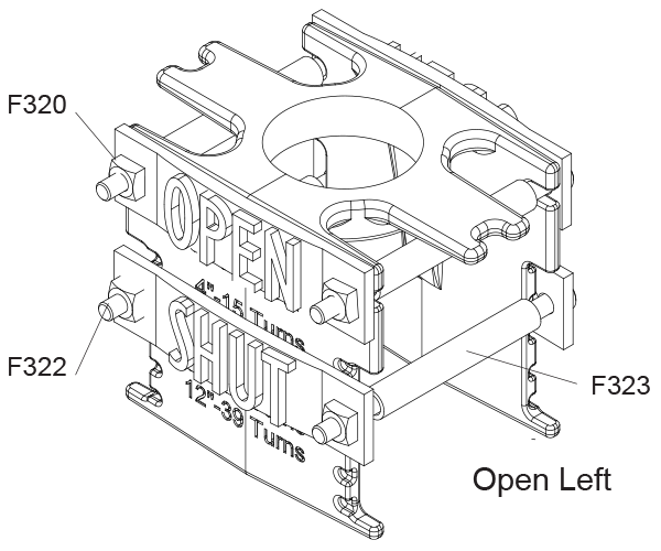
For an “open left” valve the “OPEN” sign should be mounted
above the “SHUT” sign. (Fig. 2B) For an “open right” valve the
“SHUT” sign should be mounted above the “OPEN” sign.
(Fig. 2C).
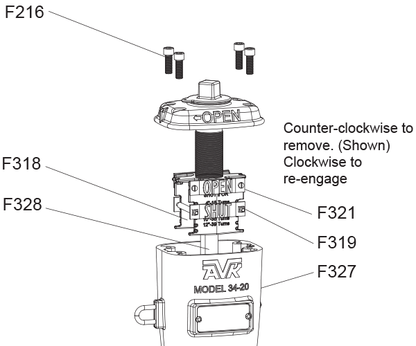
1. With a 3/8”, (10mm) allen wrench, remove the four Bonnet
Bolts (F216) attaching the Bonnet (F337), to the Head/Upper
Barrel Assembly (F327). (See Fig. 2A).
2. Pull the Bonnet and Target Assembly away from the Head/
Upper Barrel.
3. If the Post Indicator is to be mounted on an open left valve,
the “OPEN” Plate (F321) remains in the top position of the
Target (F318). (See Fig. 2B).
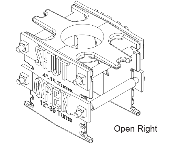
4. To configure for “open right” remove the Plate Attachment
Screws (F322), and Plate Nuts (F320) with a flat bladed
screwdriver and 7/16”,(11mm) wrench. Switch the locations
of the “OPEN” and “SHUT” Plates. The “SHUT” Plate F319,
should be mounted on top. (See Fig. 2C).
5. Re-attach the associated hardware. Ensure that the “OPEN”
Plate is in the correct location for the size of valve that the
Post Indicator is being mounted on.
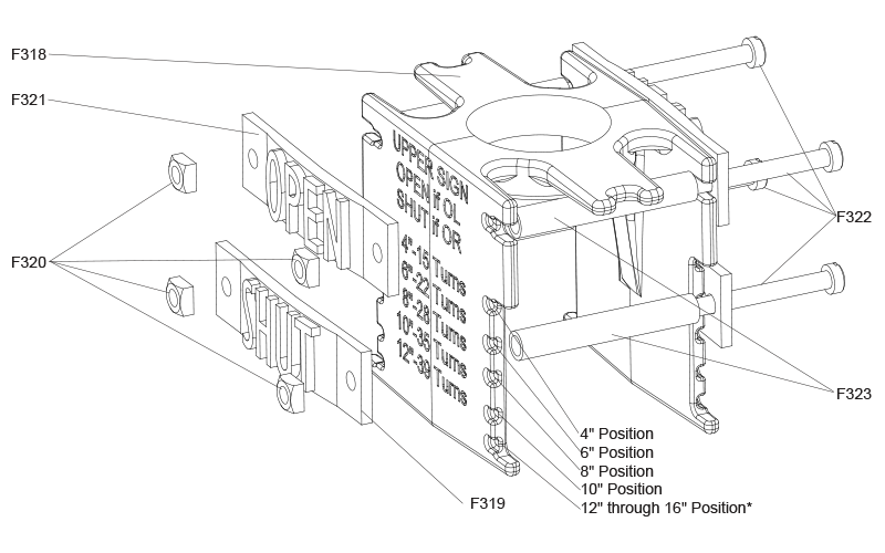
NOTE: Each set of dimples in the target is marked for the
correct valve size (4″ through (12-16″)). The Target
Spacer (F323) should always be mounted on the
Attachment Bolts that attach the “OPEN” plate.
(See Fig. 3, on page 5)
6. Lift the re-assembled post indicator Bonnet/Target Assembly
onto the Head/Upper Barrel Assembly. Make sure the upper
stem rod slides into the lower stem rod.
7. Install and tighten the four Bonnet Bolts (F216) attaching the
Bonnet (F337) to the Head/Upper Barrel Upper Barrel
Assembly (F327) .
| Cookie | Duration | Description |
|---|---|---|
| cookielawinfo-checkbox-analytics | 11 months | This cookie is set by GDPR Cookie Consent plugin. The cookie is used to store the user consent for the cookies in the category "Analytics". |
| cookielawinfo-checkbox-functional | 11 months | The cookie is set by GDPR cookie consent to record the user consent for the cookies in the category "Functional". |
| cookielawinfo-checkbox-necessary | 11 months | This cookie is set by GDPR Cookie Consent plugin. The cookies is used to store the user consent for the cookies in the category "Necessary". |
| cookielawinfo-checkbox-others | 11 months | This cookie is set by GDPR Cookie Consent plugin. The cookie is used to store the user consent for the cookies in the category "Other. |
| cookielawinfo-checkbox-performance | 11 months | This cookie is set by GDPR Cookie Consent plugin. The cookie is used to store the user consent for the cookies in the category "Performance". |
| viewed_cookie_policy | 11 months | The cookie is set by the GDPR Cookie Consent plugin and is used to store whether or not user has consented to the use of cookies. It does not store any personal data. |