 AVK SUPPORT
Expect... AVK
AVK SUPPORTLEVER AND WEIGHT
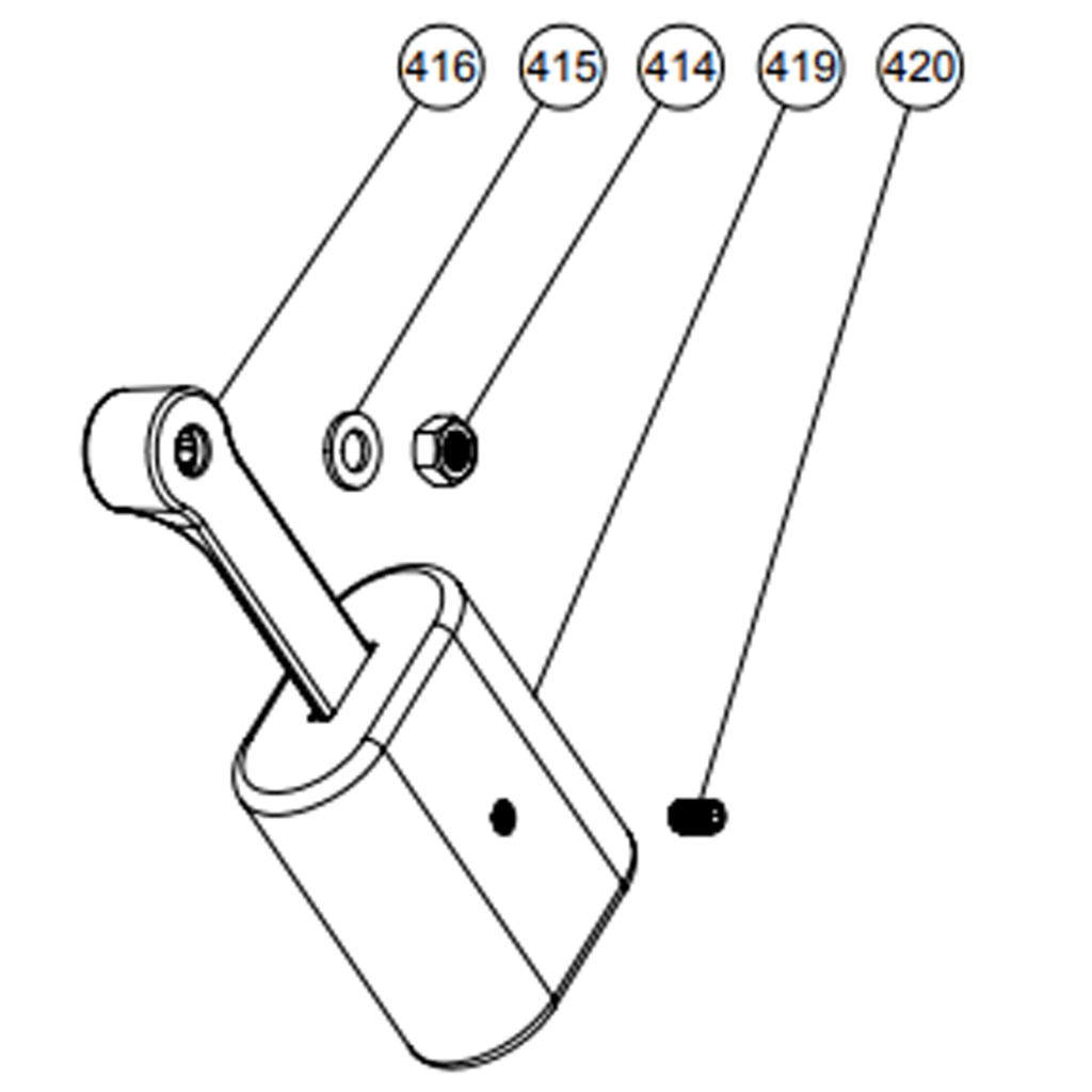
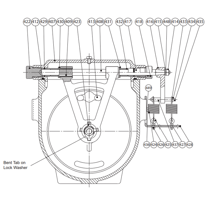
Once the valve is properly installed, the lever and weight assembly needs to be attached to the Shaft (408) passing
through the Open Bushing (417) in the Bonnet (407). Slide the Lever (416) onto the Shaft (408) and position as shown in
figure 4. Secure the Lever with the Shaft Washer (415) and Shaft Nut (414) and tighten to 30 ft-lbs. Attach the Weight (419)
and tighten the Set Screw (420) to hold the weight in place. A medium strength thread locking compound such as Locktite 242
should be used to attach the Lever and Weight.
WARNING: The weight can be moved on the lever to adjust closing speeds for optimum performance. DO not adjust
the weight while the system is operation. Serious injury can occur.
LEVER AND SPRING 3″- 8″
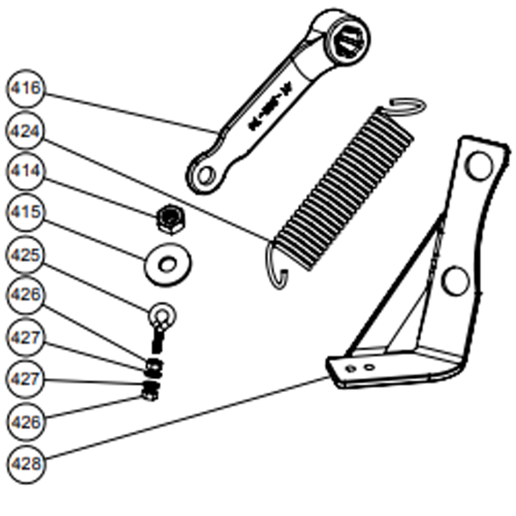
For sizes 3-inch through 8-inch, the Spring Bracket (428) must be installed using the flange mounting hardware
(figure 6). Install the Spring Eyebolt (425) on the Spring Bracket, securing it with the Spring Eyebolt Nuts (426), and Spring
Eyebolt Washers (427), one washer and nut on each side of the Spring Bracket (428). Slide the Lever (416) onto the Shaft
(408) and position as shown in figure 4. Secure the Lever with the Shaft Washer (415) and Shaft Nut (414) and tighten to 30
ft-lbs. Attach Spring (424) in it’s relaxed position as shown in figure (6).A medium strength thread locking compound such as
Locktite 242 should be used to attach the Lever.
LEVER AND SPRING 10″-12″
For Lever and Spring equipped 10-inch and 12-inch swing check valves, the Lever and Spring Assembly is installed
at the factory.
LEVER AND SPRING 10″-12″ (OPTIONAL)
For Lever and Spring equipped 10-inch and 12-inch swing check valves, the Lever and Spring Assembly is installed at the factory.
DISASSEMBLY FOR INSPECTION
For convenience, the valve can be disassembled for inspection without removing it from the pipeline. All work on the
valve should be performed by a skilled mechanic with proper tools and a power hoist for larger valves. Disassembly may be
required to inspect the ball for wear or the valve for deposits.
WARNING: The line must be isolated, depressurized, and drained before removing the valve bonnet or removing the
valve from line. Failure to do so may cause pressure to be released resulting in severe injury or death.
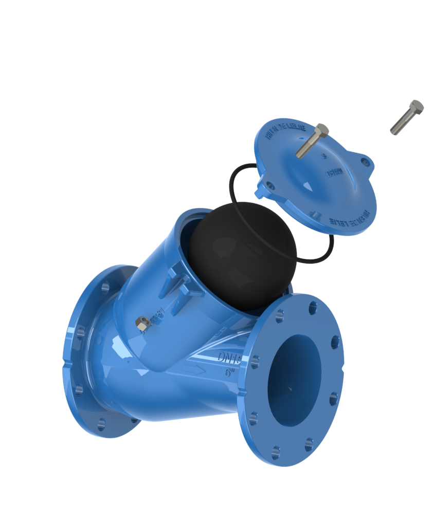
1. Isolate the valve, relieve pressure and drain the pipeline. Remove the bonnet bolts (601) and bonnet
nuts (605) from the bonnet (602).
2. Pry the valve bonnet (602) loose if required and lift off.
3. Inspect the ball (604) to see if it is worn or damaged. For larger valves, the valve may need to be removed
from the line to remove the ball.
4. Replace worn parts as necessary or replace head assembly with a new head assembly.
REASSEMBLY AFTER INSPECTION
All parts and sealing surfaces must be cleaned before reassembly. Worn parts and seals should be replaced during
reassembly.
1. Insert the ball (604) into the valve body (600).
2. Place the bonnet o-ring (603) onto the bonnet (602).
3. Place the bonnet/o-ring assembly onto the valve body (be careful not to displace the bonnet o-ring) and
fasten with the appropriate bonnet bolts (601) and bonnet nuts (605). Ensure that the bonnet
o-ring (603) is not being pinched between the bonnet (602) and valve body (600).
4. Tighten the bonnet bolts (601) to 45 ft-lbs incrementally in a crossover pattern to ensure that the bonnet
(602) does not bend or crack and the bonnet o-ring (603) is evenly compressed.
| Cookie | Duration | Description |
|---|---|---|
| cookielawinfo-checkbox-analytics | 11 months | This cookie is set by GDPR Cookie Consent plugin. The cookie is used to store the user consent for the cookies in the category "Analytics". |
| cookielawinfo-checkbox-functional | 11 months | The cookie is set by GDPR cookie consent to record the user consent for the cookies in the category "Functional". |
| cookielawinfo-checkbox-necessary | 11 months | This cookie is set by GDPR Cookie Consent plugin. The cookies is used to store the user consent for the cookies in the category "Necessary". |
| cookielawinfo-checkbox-others | 11 months | This cookie is set by GDPR Cookie Consent plugin. The cookie is used to store the user consent for the cookies in the category "Other. |
| cookielawinfo-checkbox-performance | 11 months | This cookie is set by GDPR Cookie Consent plugin. The cookie is used to store the user consent for the cookies in the category "Performance". |
| viewed_cookie_policy | 11 months | The cookie is set by the GDPR Cookie Consent plugin and is used to store whether or not user has consented to the use of cookies. It does not store any personal data. |